Electrical Resistivity Monitoring Primer
Electrical Resistivity Method
The objective of the electrical resistivity method (similar to all geophysical methods) is to obtain information about the subsurface. As implicit in the name, in the electrical resistivity method we obtain this information from measuring and interpreting the electrical properties of the subsurface.
This involves the following steps:
- Measuring the electrical resistivity of the subsurface at different locations using a special instrument (a resistivity meter)
- Processing these measurements into a 1D, 2D, 3D, or 4D distribution of electrical properties of the subsurface and
- Interpreting this distribution in the context of certain questions.
As the electrical resistivity is a function of different properties of the subsurface (such as porosity, saturation, water chemistry, lithology, biogeochemical processes, and temperature) electrical resistivity is a very versatile method.
Resistivity measurements
The standard method of measuring electrical resistivity is through a four electrode measurement in which we use two current electrodes and two potential electrodes. Such a measurement is schematically shown in the figure below.
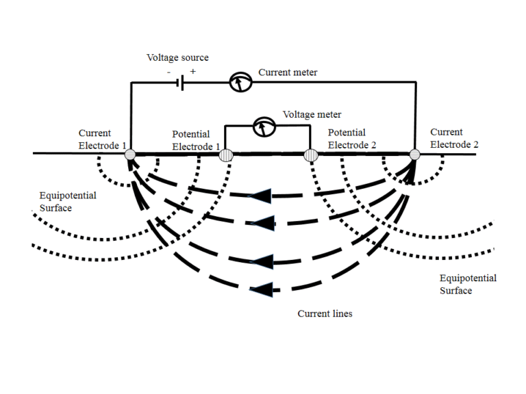
Four electrode measurement
In a four electrode measurement we apply a direct current voltage across two electrodes (known as the current electrodes). This creates a current and an associated potential field in the subsurface. We can now measure both the current between the current electrodes and the electrical potential across two other electrodes (the potential electrodes). From the current (in Amperes) and potential (in Volts) we can calculate a so called transfer resistance with Ohm’s law (R=V/I). This transfer resistance is a function of the electrical properties of the subsurface and the electrode geometry.
Practical details of measurements
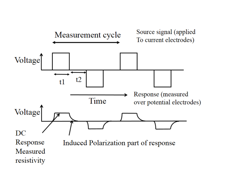
For a variety of reasons it is common in practice to collect and average data over a few cycles in which (as shown in the figure below) the polarity of the voltage applied over the current electrodes is reversed. In general this cycle will include a period in which no current is injected. The current and resulting voltage are measured for each cycle and averaged or stacked to give a single measurement. This thus consists of a current (given in Amperes, A) and an associate measured voltage (given in Volts, V). Note that as shown in the figure on the right this measurement can also have an induced polarization part (resulting from the fact that the earth acts both as a conductor and a capacitor).
Sensitivity of measurements
Resistivity measurements are sensitive to the electrical resistivity distribution in a volume in the subsurface. The size and shape of this volume depends both on the electrode geometry and on electrical resistivity values of the subsurface. For instance, if we have a very conductive layer in the upper meter of the earth then most of the current will be channeled in this layer, and we will be less sensitive to deeper layers. In general our measurements will be more sensitive to properties near the electrodes. We can numerically calculate the size and shape of the sensitivity volume. A detailed technical discussion on this type of analysis can be found in a 2003 article by Alex Furman in Vadose Zone Journal.
Apparent resistivity vs transfer resistance
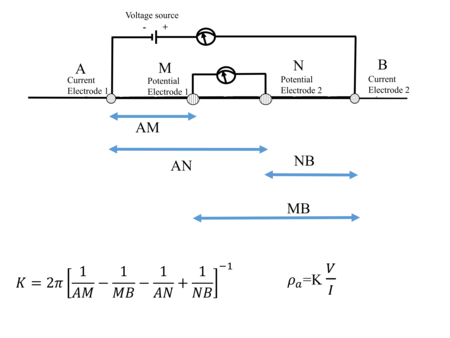
From the figure above it is obvious that the transfer resistance is a function of both subsurface properties and electrode geometry. By considering the geometry of the electrodes we can calculate a geometric factor K (see the figure below) which can be used to calculate what is known as the apparent resistivity ρ a (which is given in Ohm.m). The apparent resistivity is used extensively for visualization as it allows a simple way to compare measurements done with different electrode spacings. Note that (for historical reasons) the current electrodes are often referred to as A and B, and the potential electrodes as M and N.
Need for multiple measurements
The objective of the electrical resistivity method is to find a volumetric distribution of subsurface electrical properties. For this we need to take multiple measurements with different electrode combinations. For this, a number of standard geometries have evolved which are typically encountered. Details on these geometries and data acquisition are provided here.
Self potential and complex resistivity/induced polarization measurements
There are three related methods in which we use galvanically measured (ie through the contact of an electrode with the soil) electrical properties of the subsurface which are commonly encountered. The method described here (and the focus of the primer) is the most prevalent one, and the one typically referred to as electrical resistivity. Two other ones are the self potential method and complex resistivity or induced polarization methods. In the self potential method we measure the naturally occurring potential. In the complex resistivity and induced polarization methods we measure the complex conductivity. This is associated with capacitive properties of the subsurface. Sometimes the same instrumentation can be used for al three methods, sometimes specialized instrumentation is needed.